Components and function of steel open web girder.

A truss is a structure that acts like a beam while components or members, subjected to primarily axial stresses. The members are arranged in triangular patterns. Ideally, the end of each member at a joint is free to rotate independently of the other members at the joint.
If this does not occur, secondary stresses are induced in the members. Also if loads applied other than at panel points, bending stresses are produced in the members. Truss may be either through type or deck type. In the deck type carriage way is supported on Top Chord while in through type, carriage way is supported on Bottom Chord.

Structural members of the floor system are designed and located such that load from carriageway is passed through the nodal point of the truss so as to have axial stress in the member joining the panel point. Primary members are chord members and web members. Chord members (TOP and Bottom chord) resist bending moment in the form of direct tension and compression, certainly in opposite direction with a lever arm of length equal to Centre to Centre distance of Top and Bottom chord. Web members, carry shear force also in the form of direct tension and compression in the subject members.
In Indian Railway, open web through standard girder spans are used as 30.5m, 45.7m, 61.0m and 76.2m. For rail cum road bridges spans to 91.0 m and 122.2 m are also used in small numbers. Mostly open web type girders are used over valleys and large rivers on account of economy in cost. Being rail level at a shorter distance from the bottom level of through type girder and major part of the girder is above the deck it requires reduced bank height while comparing with plate girder, underslung girder, hence open web through girders are cost effective.
Panel points: These are joints at the intersection of centroidal axis of truss members. L0, L1, L2 etc are the panel points as shown in the fig of typical warren type open web through girder. Deck Load is transferred by the cross girder connected at the panel point with bottom chord inner web such that axial force is generated in the members connecting the panel point.
 a) Bottom chord - This is designated as L0 - L1 - L2 etc. and made up of rolled or
built up channels placed at a distance apart and connected with
batten plates at top and bottom. A typical section of Bottom chord for 45.7m span is shown in fig.
a) Bottom chord - This is designated as L0 - L1 - L2 etc. and made up of rolled or
built up channels placed at a distance apart and connected with
batten plates at top and bottom. A typical section of Bottom chord for 45.7m span is shown in fig.
This is tension member of a simply supported girder and act like the bottom flange of a beam/plate girder. They resist axial tensile forces.
b) Top chord - These are subjected to axial compression. Top chord members are designated as U1 -U2 -U3 etc. in the fig top. A typical section of Top chord is shown in fig below.

This act like the Top flange of a beam/plate girder resisting axial compression.
c) Web Member: Consists of vertical and diagonal members. Inclined members are subjected to alternately tension and compression from end towards the Centre due to dead load. First diagonal U1-L2 is a tension member and second diagonal member L2-U3 is a compression member. However, due to position of live load these diagonal members are also subjected to reversal of stresses, So these are called reversible stress members. Web members i,e diagonal and vertical both resist shear force.
Vertical Web Members: All members vertical to chords are vertical web members. Members connecting odd number panel points (i.e. L1 -U1, L3-U3 ) are tension members and members connecting even number panel points i.e. U2 -L2, U4-L4, are called redundant members as they carry only dead load stresses and provide rigidity to truss and reduce unsupported length of top chord. Members connecting odd number panel points (i.e. L1 -U1 ) are tension members and members connecting even number panel points i.e. U2 -L2 are called redundant members as they carry only dead load stresses and provide rigidity to truss and reduce unsupported length of top chord.
d) End Rakers - Inclined members at either end of the truss, i.e. L0 -U1 are called end racker as in fig top. It is a compression member and heaviest member of truss. Section of this member is similar to that of top chords. This member in addition, transfers racking force and wind force, etc. to bearings. In this connection, it is mentioned that Racking Force is a lateral force produced due to the lateral movement of rolling stocks in railway bridges. Lateral bracing of the loaded deck of railway spans shall be designed to resist, in addition to the wind and centrifugal loads.
e) Deck: The deck is the structural element providing support to the vehicular loads. Where the deck is located near the bottom chords in open web through girder, deck is supported by a floor system consisting of cross girder, stringer. Following are the members of floor system of through span :
1) Cross girder - Both trusses at each panel point of bottom chords are connected by cross beams/cross girders. A typical cross girder section at its centre is shown in fig.

This member is built up I-section with web plate, top and bottom flange plates. Web is strengthened with angle stiffeners of riveted connection at the middle length. In addition there are plate stiffeners on either side of web at 02 location where stringer is web connected with the Cross girder. The end cross girders are provided with additional stiffeners and pad plates to facilitate lifting of the girders by jacks for maintenance work. Cross girders at other panel points are known as intermediate cross girders.
Cross girders are used to stiffen the the main girder in lateral direction. Main girders are made strong in the direction it has to resist the external moment. In the lateral direction these are made weak as an individual member to make them cost effective, although they are subjected to some forms of occasional lateral forces due to wind, storms, flood water, oscillation of vehicle, accidental forces and so on which they shall be capable to take. Further due to compressive forces developed in the top flange of the main girder there is a serious issue of buckling failure of the main girder in the lateral direction.
To take care of it, some members are connected in between parallel main girders, across the axis of Main girder at a certain interval. These members are also called diaphragm which stiffens the main girder enabling it to take a large amount of force in the lateral direction.
2) Rail bearers or stringers - Stringers also known as Rail bearer in Railway bridge are a pair of longitudinal members, set parallel to the direction of traffic. Rail bearers are connected between two successive cross girders.

They are used to transmit the deck loads to the floor beams/cross girders which again transfers the load to the connected main truss girder on either end. A typical section of stringers consisting of web plate and flange plates to form I-section is shown in fig. Diaphragm with lateral bracing are provided to stringers to give it lateral rigidity shown in the fig below. Sleepers rest on top flange of stringers and are anchored with hook bolts.
 |
| DIAPHRAGM TO INCREASE LATERAL STABILITY TO STRINGER. |
Following are some important secondary members of open web through spans:
(a) Bottom lateral bracings (b) Top lateral bracings (c) Sway bracings and knee sway (d) Portal bracings and knee portal (e) End bracket (f) Main gussets (g) Bearings

a) Bottom lateral bracings: These are provided in each panel (below rail bearer) and diagonally connected to bottom chord panel points with gussets as in fig Bottom Plan. These bracings are also connected with hanger plates to bottom flanges of rail bearers to facilitate transferring the longitudinal forces due to Rail wheel interaction to bottom chord panel points. In this connection, it is mentioned that longitudinal forces are set up between vehicles and bridge deck when the former accelerate or brake. Where a structure carries railway track, longitudinal loads are arising due to the tractive effort of driving wheels of locomotives depending on traction characteristics of locomotive also due to braking force resulting from the application of brakes.
b) Top lateral bracings shown in the typical top plan above are provided in each panel (between sway bracings) and diagonally connected to top chords with top lateral gusset plates to resist wind force as well as for lateral rigidity shown in fig above. Being the top chord a long compression member, there will have a tendency to deform in cross direction even due to vertical load, leading to twisting of the whole girder. Once the girder has twisted / tilted a horizontal component of vertical load will act into play in the lateral direction i.e weaker axis if it is not braced. Unbraced top chord is unable to resist any kind of horizontal load, even vertical load also. Lateral bracings and sway bracings together keeps the two main trusses in perfect vertical thus enabling them to carry the design forces and no horizontal forces comes into play due to buckling of top chord.
c) Sway bracings shown in a typical Plan above. These are provided in webs of top chords at intermediate panel points for lateral rigidity. One strut is provided between bottom flange of sway bracing connected to the vertical and is called knee sway bracing.
d) Portal bracings are made up of beam type or frame type and connected at either end panel points partially to top chord and partially to end raker. Knee portal struts or frames are connected to end rakers.
e) End brackets made up of web plates and angle cleats are provided to end cross girders in line with the stringers to one end of a span in multiple span bridge or at both ends in single span bridge. This ensures proper sleeper spacing.
f) Main gussets are made up of 20 mm thick plates for connecting members at every panel point of top and bottom chords.
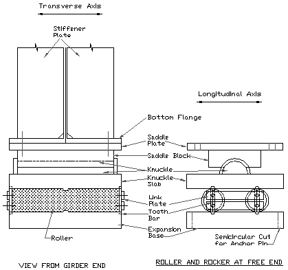
g) Bearings of open web through spans are provided with one end as free end for expansion called as rocker and roller bearings. Other end of span is provided with fixed end bearings called as rocker bearings. Bearings are connected with turned bolts between saddle plate and bottom chord at either end.

According to the position of carriageway bridges may be classified as "deck type", "through type" or "semi-through type"
(i) Deck Type Bridge - Bridges constructed with plate girders and under slung girders are deck type bridge. In the deck type bridge, the roadway or railway is placed on the top flanges/top chord of the girder.
(ii) Through Type Bridge - All open web girder bridges are through bridge, the roadway or railway is placed at/near bottom Chord level. Maximum part including Top bracing system lies above the deck so that traffic passes through the girder in between top and bottom chord.
(iii) Semi through Type Bridge - The deck lies in between the top and the bottom flanges/chord. There is no scope of bracing at the top chord level and part of the main girder is projected above the Road level. The lateral restraint in the system is obtained usually by the U-frame action of the verticals and cross girder acting together.
Other type bridges:

Main components of plate girders are
1. Top Flange Plate.
2. Web which connecting top and bottom Flange plate.
3. Bottom Flange plate.
4. Vertical stiffeners also known as transverse stiffener are of 02 types.
a) Bearing Stiffeners
b) Intermediate stiffeners
5. Horizontal stiffeners
Top flange and Bottom flange plate: These two plate together resist external bending moment by forming a couple of compressive force in the top plate and a tensile force in the bottom flange plate in opposite direction with a lever arm having distance between top and bottom flange. Deeper the web plate, higher is the resisting moment, however it shall be limited as per codal provision.
Web: It is a deep and thin plate connecting Top and bottom plate resisting shear force developed due to external loading.
Vertical stiffeners: These are connected along the depth of the web plate in between flange plates serves two important roles as bearing stiffener and as intermediate stiffeners.
Bearing stiffeners are fixed at both end of the girder and transfers the load to the substructure through bearing.

To get maximum benefit these are provided at the centre of the bearing and protects the thin web plate from crushing which alone are not capable to transfer the load. Bearing stiffeners are generally having larger cross section compare to the intermediate stiffener.
Intermediate stiffeners are required when there are concentrated loads acting on the plate girder. When the thickness of the web is very less (10 to 12mm even for a deep girder of 1200), then the web may buckle due to shear. In that scenario, intermediate stiffeners are provided in order to improve the buckling strength of the web.
Horizontal stiffeners are provided in parallel to the flange plates. They are also called as longitudinal stiffeners. These stiffeners will improve the buckling strength of the
TYPES OF DIFFERENT BRIDGES:
ARCH SLAB BEAM/GIRDER TRUSS CANTILEVER SUSPENSION CABLE STAYED
ARCH BRIDGE:

1. Very Oldest type bridges more than even thousand years, generally brick and stone masonry.
2. High strength massive structure.
3. Superstructure load is distributed along the centre of the curved arch, subjected to almost axial compressive force for which brick/stone masonry is very appropriate.
4. The force is transferred to the massive abutment generally in 02 components. Vertical component is resisted by the soil below the substructure. Horizontal component is taken by the earth retained.
5. Its construction mechanism does not allow any tension in the arch masonry which is inherently weak in tension.
6. In multi-span arch bridge horizontal thrust for the intermediate span are balanced, thereby piers are subjected to vertical load only.
Some Important Features:
1. 24.4m Composite Girder : 450 sqm, painting area
2. 45.7m QWG: 2500 Sqm, painting area
3. weight of 45.7m OWG: 134.33Tonne.
4. weight of Channel sleeper 175mm: 150 Kg.
5. weight of Channel sleeper 150mm: 125Kg.
6. Weight of H-Beam: 150 Kg.
7. Butterfly Passenger Shed: Size 16 m x 5.5 m. cost: 6.7 Lakhs e/c Foundation and seating arrangement.
8. 24m composite girder/ RDSO 11751, Single Track Railway Bridge
a. Volume of Slab concrete-42.08 cum
b. Reinforcement: 10884 Kg
c. Shuttering Area for slab: 235 sqm.
d. Overall width of slab outer= 5.2m
e. Overall width inner= 4.8m
f. Clear Span 24.4m
g. CRS of Bearing=25.28m
h. Overall length of slab = 26.16m.
i. C/C of pier=26.20m
j. Wearing coat 25mm thk.
k. Structural steel due to inspection Platform, Pathway Railing,
inspection ladder, rungs, Pathway Frame/Girder i/c 10%: 4.5 MT.
l. Painting Area of 'k' above= 130 Sqm
m. Chequered Plate for pathway: 1400Kg.
n. HSFG Bolts: 2373nos @ 0.4 kg=950 Kg i/c 10% misc.
o. Metalizing Area= 450 Sqm.
p.Total height from formation top to abutment cap top:
0.025 + 0.28 + 0.1 + 1.886 + 0.186 = 2.477m.
r. height from rail level to rail level in ROR=3.0m
s. Volume of concrete for Inspection Platform for 01 abutment : 3.5 Cum
t. Steel weight of 01 span girder : 50.34MT
u. net weight of bar= 10.884MT
(Above data is for Estimate purpose only)
FREQUENTLY REQUIRED DIMENSION OF COMPOSITE GIREDER:
Girder R/lvl to Bot. of Height of R/lvl to R/Lvl
Girder bearing i/c Top & in ROR
300 Cushion Bot/Plate
12.2 m 2040 176 7540
18.3 m 2472 161 8972
24.4 m 2959 186 9459
30.5 3420 219 9920


0 Comments